Showing posts with label Electrical Simple question & answer. Show all posts

Friday, 19 February 2021

How Power Factor Correction Capacitors Solve the Problem of Low Power Factor.

 How Power Factor Correction Capacitors Solve the Problem of Low Power Factor.

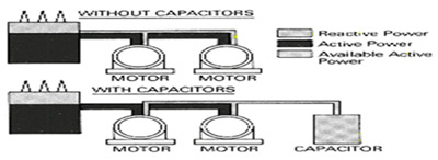
Low power factor is a problem that can be solved by adding power factor correction capacitors to the plant distribution system. Correction capacitors work as reactive current generators “providing” needed reactive power (kvar) into the power supply. By supplying their own source of reactive power, the industrial user frees the utility from having to supply it, therefore, the total amount of apparent power supplied by the utility will be less.


Role of Capacitors


Power factor correction capacitors reduce the total current drawn from the distribution system and subsequently increase system capacity by raising the power factor level.

Sunday, 16 August 2020

Why we improve power factor

 Low power factor means poor electrical efficiency. The lower the power factor, the higher the apparent power drawn from the distribution network.

When low power factor is not corrected, the utility must provide the nonworking reactive power in addition to the working active power. This results in the use of larger generators, transformers, bus bars, wires, and other distribution system devices that otherwise would not be necessary.
As the utility's capital expenditures and operating costs are going to be higher, they are going to pass these higher expenses to industrial users in the form of power factor penalties and higher utility bills.

Sunday, 16 February 2020

Difference Between Linked Fuse and MCCB

Linked Fuse 

- According to price linked fuse is cheap 
- Installation can be done easily
- Once it sense the over current it will burn-out , then you have to replace it with a new one 
- Replacing may cause delay and you may to shutdown the circuit
- It may cause fire while burning-out
- Small in size compared to MCCB
- Suited for only less than 100Amps
- Eg : HRC Fuse , Cartridge Fuse 

MCCB

- Costlier than Linked fuse
- Easy to install and operate
- Instead of linked fuse we can vary the current limit range in the MCCB
- Totally safer to use 
- Easy to re-energize the circuit after the fault detection 


Wednesday, 11 April 2018

What is power factor

Index

  •  Power  Factor
  • Types of power factor
               1. Lagging power factor
                2. Leading power factor
              2. Using Synchronous Condenser
              3.Phase Advanser
  

What is power factor?


      The ratio of the active power (P), measured in KW and the apparent power (S), measured in KVA is defined as the power factor.
      Also,the power factor is used to represent the fraction of total energy that is used for doing useful work and the fraction of energy is stored in the form of magnetic energy in the inductor and capacitor of the circuit, and its values lies between 0 and 1.
     The most economical value of power factor lies between 0.9 and 0.95. The power factor of the circuit can be lagging ,leading and unity.


1.      The ratio between actual power and apparent power is called power factor
Actual or real power = KW
Apparent power = KVA
Power factor = KW/KVA
2.      The cosine of angle between current and voltage is called power factor
3.      The ratio between resistance and impedance is called power factor

1. Lagging power factor. 

  Lagging power factor means ,"If  the current (I) flowing in the circuit leads voltage (E) in the circuit, then the power factor is said to be lagging ".


                       The pictorial representation of the lagging power factor, based on the phase angle between the voltage (E)  and current (I). 


2. Leading power factor 


 Leading power factor means ,"If the voltage (E) in the circuit leads the current (I) flowing in the circuit, then the power factor is said to be leading ".

               The pictorial representation of the leading power factor, based on the phase angle between the voltage (E)  and current (I). 


Causes of low power factor.


The different causes of low power factor are given below :
  •  Single-phase and three-phase induction motors, which are normally used in AC circuits, where the current lags the voltage by 90`, as it is purely inductive in nature.
  •  Other inductive equipment, which cause low power factors are :transformers,generators, arc lamp,electric furnaces and so on.
  •  Load variation in the power system i.e., if the power system is loaded lightly, the power factor becomes low, as the current drawn by the equipment increases due to increases in voltage.
  •  Existence of harmonic current reduces the power factor.
  •  Imbalance in the power system due to improper wiring or electrical accident.

    Disadvantages of low power factor .

  • Current drawn by the circuit will be high.
  • Copper loss in the equipment will be high and hence, the efficiency of the equipment decreases.
  • Equipment gets overheaded due to the copper loss, which in turn increases the stress on the insulation of the cable and makes it weak.
  • As the current drawn by the circuit increases, the size of the conductor has to be increased to carry such current, which in turn increases the cost.
  • Increases the KVA rating of the machine, which increases the size of the equipment, thereby increasing the cost.
  • Voltage drop in the equipment will be increased, thereby affecting the voltage regulation of the equipment.
  • Leads to decrease in the active power, which results in uneconomic operation of the equipment.

Power factor  Improvement or Correction :


   If the power factor of the system is low, improvement or correction of power factor is necessary. Adjusting the power factor of the system closer to unity using some equipment is known as power-factor improvement or correction.Power factor improvement or correction reduces the apparent power consumed by the load and hence, the current drawn by the load will decreases. In other words, power factor correction or improvement is the injuction of reactive power into the circuit to neutralize the effect of lagging current. Static capacitors or synchronous condensers or phase advancers are used to improve or correct the power factor of the system.

Using Static Capacitors :


    Static capacitors, whose ratings vary from 15 kVAR to 10000 kVAR, are used as devices to improve or correct power factor of the system. In a three- phase system, the capacitors arranged in star or delta connection arc used to improve the power factor.

Advantages of Static Capacitors:

  1. Simplest method of power factor improvement or correction.
  2. Maintenance required in the system is less.
  3. Easier installation and less weight.

Disadvantages of Static Capacitors:

  1. Life span of capacitor is short i.e.,8-10 years.
  2. Gets easily damaged due to over voltages.
  3. Once the capacitor is damaged, it is difficult to replace.
  4. Production of switching surges and harmonics happen due to constant switching.

                                                                                                                                                                             Applications of Static Capacitors:


                           Capacitors in the range of a few hundred kVAR are used in industrial distribution circuits; capacitors of 500-3000 KVAR rating are used in small distribution substations and those with larger ratings are used in large substations.


Using Synchronous Condensers:


            The working of a synchronous motor can be varied, based on the excitation given to its windings. The excitation to the winding is classified as over-excitation, under-excitation and normal-excitation. A synchronous motor in over-excitation and no load condition draws leading current and starts to act like a capacitor and is known as a synchronous condenser. Varying the field excitation can control the amount of kVAR supplied to the load using synchronous condensers.

Advantages of Synchronous Condensers:

  1. Life span of the equipment is longer i.e.,almost 25 years.
  2. Power factor control is fexible and reliable.
  3. Harmonics have no effects on synchronous condensers , as ther is no switiching mechanism.

Disadvantages  of Synchronous Condensers:


  1. Losses in the synchronous condensers are high.
  2. They are expensive and have a high maintenance cost.
  3. The noise generated by them pollutes the environment.
  4. Auxilliary device is required , as a synchronous condenser is not self- starting.
  5. Use synchronous condenser is uneconomical for equipmnt below 500 kVA.

      Applications of Synchronous Condensers:


                       Synchronous condensers are used in large factories, industries and large substations to improve the power factor and voltage regulation.


Using Phase Advancers:


        In a induction motor, the power factor is low, as the stator winding draws lagging current from the supply. Phase advancer, which can be used only in induction motors to improve the power factor, ia a simple AC exciter. It is mounted on the shaft of the induction motor and is connected to the rotor circuit. Phase advancer supplies exciting ampere-turns to the rotor circuit of induction motor at slip frequency, which improves the power factor of the induction motor.


Thursday, 20 October 2016

Advantages and disadvantages of synchronous motors


Advantages and disadvantages of synchronous motors


Advantages of synchronous motors


1. The speed is constant and independent of load. 

2. These motors usually operate at higher efficiency

3 .Electromagnetic power varies linearly with the voltage.

4. These motors can be constructed with wider air gaps than induction motors, which make them              better mechanically.

5. An over excited synchronous motor having a leading power factor can be operated in parallel with     induction motors.

                                                                                                                    Read more

Monday, 23 May 2016

Application of synchronous motors

Application of synchronous motors


     1. They are used in power houses and substations in parallel to the bus-bars to improve the power            factor.

     2. Synchronous motors are also used to regulate the voltage at the end of transmission lines.

     3. In factories having a large number of induction motors, or other power apparatus operating at              lagging power, they are employed to improve the power factor.

     4. Typical applications of high speed synchronous motors are such drives as fans, blowers, dc                   generators, lines shafts, centrifugal pumps and compressors, reciprocating pumps and constant              speed frequency changers, rubber and paper mills etc.

What is synchronous motor

What is synchronous motor

     
     1. The synchronous motor is one type of 3 phase A.C motor which operate at a constant speed                 from no load to full load.

    2. It is similar in construction to 3-phase A.C generator in that it has a revolving field which must           be separately excited from a D.C source.

     3. By changing the D.C field excitation,the power factor of this type of motor can be varied over a          wide range of lagging and leading values.

     4. This motor is used in many application because of its fixed speed from no load to full load, its             high efficiency and low initial cost.

     5. It is also used to improve the power factor of 3 phase AC industrial circuits.

Wednesday, 11 May 2016

Why alternators are rated in kva and not in kw?

Why alternators are rated in kva and not in kw?


     Apart from constant loss, the variable loss which occurs in alternators is the copper loss, occurring in the 3-phase winding which depends of R and the square of the current delivered by the generator, As the current is directly related to the apparent power delivered by the generator, the alternators have only their apparent power in VA/KVA/as their power rating.

What is synchroscope?

What is synchroscope?

     The best method of synchronizing alternator is by means of a single phase device known as synchroscope, which provides a more accurate indication of synchronization.

Why alternators are synchronized in power plant?

Why alternators are synchronized in power plant?


    In power stations, alternators are operated in parallel to supply the total load. The need for parallel operation arises due to the following reasons.

     1. The total load requirement cannot be met by a singe alternator.
     
     2. Parallel operation increases reliability of electric supply. An outage of one alternator will not              cause total power loss to the load

     3. If alternators are operating in parallel, one or more of them can be shut down for preventive     
         maintenance in turn.
     
     4. Parallel operation of alternators leads to economy in operating costs. The less efficient machine          can be shut down when the load requirement is less.

What are the conditions for parallel operation of an alternator


What is an excitor?

What is an excitor?


     An excitor is a small generator (usually flat compound wound type ) to supply dc power to the field magnet system or rotor of the alternator. 

Monday, 9 May 2016

What are the losses in the alternators ?

What are the losses in the alternators ?

1. Copper losses 

2. Iron losses 

3. Friction and windage losses .

What is an armature reaction ?

What is an armature reaction ?


     When the alternator is loaded, current flow through the armature winding which establishes its own flux. there are two fluxes in the air gap. First flux is main flux due to the current through the field winding. Second flux is armature flux, due to the current through the armature. The effect of armature flux on main flux is armature reaction. 

What are the causes of changes in voltage of alternators when loaded

What are the causes of changes in voltage of alternators when loaded


      1. voltage drop due to resistance of winding 
      
      2. Voltage drop due to leakage reactance .
     
      3. Voltage drop due to armature reaction .

How will you adjust the frequency of an alternator

How will you adjust the frequency of an alternator 


     Frequency of an alternator can be adjusted by varying the speed of the prime mover ( as frequency (F) is proportional to speed (N) )


What is the principle of an alternator

What is the principle of an alternator 


     The alternator works on the principle of faraday,s law of electromagnetic induction. Whenever a conductor links with a magnetic field either the conductor is moving or the field is moving an emf is induced in the conductor.


What is an alternator

What is an alternator 


     An alternator or AC generator is a synchronous machine which converts mechanical energy into electrical energy and produces alternating emf.

Alternator

Saturday, 7 May 2016