DROP DOWN

Thursday 17 November 2016

What is parasitic capacitance

What is parasitic capacitance? (April/May 2010)

In electrical circuits, parasitic capacitance is an unavoidable and usually unwanted capacitance that exists
between the parts of an electronic component or circuit simply because of their proximity to each other

Why inductors are difficult to fabricate in integrated circuits

No satisfactory integrated circuits exist if high Q inductors with inductance of values larger than 5 micro Henry are required they are usually supplied by a wound inductor which is connected externally to the chip. Therefore the use of inductor is normally avoided when integrated circuits are used.

What are the major categories of integrated circuits

Based on IC Technology
Monolithic
Hybrid
Based on Active devices
Bipolar
Unipolar
Based on isolation technique
PN junction
Dielectric
Based on types of FET
MOSFET
JFET

List the advantages of integrated circuits over discrete components circuits

1 . Miniaturization and hence increased equipment density.
2. Cost reduction due to batch processing
3. Increased system reliability due to the elimination of soldered joints
4. Improve functional performance
5. Matched devices
6. Increased operating speed

Explain why buried layer is needed

In general bipolar integrated circuits use epitaxial layer process in which resistivity epitaxial is formed over low  resistivity substrate to provide isolation between the epitaxial growth and the substrate the doping used in both layers is of opposite type due to this heavily doped buried layer is formed. The buried layer is also called diffusion layer.

What is Ion implantation

The conductivity of the semiconductor increases when small impurity is added to it the process of adding impurity is called doping while the impurity to be added is called dopant so Ion implantation is a process of adding dopant to the Silicon substrate. The ion implantation process is controllable reproducible and also there are no unwanted side effects.

What is mean by diffusion

The process of introducing impurities in to the selected regions of silicon wafer is called diffusion. The rate at which various impurities diffuse into the Silicon will be of the order of 1 micro metre per hour at the temperature range of 900 degree Celsius 1100 degree Celsius. The utility and terms of the tendency to move from regions of Ion concentration to lower concentration.

Thursday 20 October 2016

Advantages and disadvantages of synchronous motors


Advantages and disadvantages of synchronous motors


Advantages of synchronous motors


1. The speed is constant and independent of load. 

2. These motors usually operate at higher efficiency

3 .Electromagnetic power varies linearly with the voltage.

4. These motors can be constructed with wider air gaps than induction motors, which make them              better mechanically.

5. An over excited synchronous motor having a leading power factor can be operated in parallel with     induction motors.

                                                                                                                    Read more

Monday 23 May 2016

Application of synchronous motors

Application of synchronous motors


     1. They are used in power houses and substations in parallel to the bus-bars to improve the power            factor.

     2. Synchronous motors are also used to regulate the voltage at the end of transmission lines.

     3. In factories having a large number of induction motors, or other power apparatus operating at              lagging power, they are employed to improve the power factor.

     4. Typical applications of high speed synchronous motors are such drives as fans, blowers, dc                   generators, lines shafts, centrifugal pumps and compressors, reciprocating pumps and constant              speed frequency changers, rubber and paper mills etc.

What is synchronous motor

What is synchronous motor

     
     1. The synchronous motor is one type of 3 phase A.C motor which operate at a constant speed                 from no load to full load.

    2. It is similar in construction to 3-phase A.C generator in that it has a revolving field which must           be separately excited from a D.C source.

     3. By changing the D.C field excitation,the power factor of this type of motor can be varied over a          wide range of lagging and leading values.

     4. This motor is used in many application because of its fixed speed from no load to full load, its             high efficiency and low initial cost.

     5. It is also used to improve the power factor of 3 phase AC industrial circuits.

Wednesday 11 May 2016

Why alternators are rated in kva and not in kw?

Why alternators are rated in kva and not in kw?


     Apart from constant loss, the variable loss which occurs in alternators is the copper loss, occurring in the 3-phase winding which depends of R and the square of the current delivered by the generator, As the current is directly related to the apparent power delivered by the generator, the alternators have only their apparent power in VA/KVA/as their power rating.

What is synchroscope?

What is synchroscope?

     The best method of synchronizing alternator is by means of a single phase device known as synchroscope, which provides a more accurate indication of synchronization.

Why alternators are synchronized in power plant?

Why alternators are synchronized in power plant?


    In power stations, alternators are operated in parallel to supply the total load. The need for parallel operation arises due to the following reasons.

     1. The total load requirement cannot be met by a singe alternator.
     
     2. Parallel operation increases reliability of electric supply. An outage of one alternator will not              cause total power loss to the load

     3. If alternators are operating in parallel, one or more of them can be shut down for preventive     
         maintenance in turn.
     
     4. Parallel operation of alternators leads to economy in operating costs. The less efficient machine          can be shut down when the load requirement is less.

What are the conditions for parallel operation of an alternator


What is an excitor?

What is an excitor?


     An excitor is a small generator (usually flat compound wound type ) to supply dc power to the field magnet system or rotor of the alternator. 

Monday 9 May 2016

What are the losses in the alternators ?

What are the losses in the alternators ?

1. Copper losses 

2. Iron losses 

3. Friction and windage losses .

What is an armature reaction ?

What is an armature reaction ?


     When the alternator is loaded, current flow through the armature winding which establishes its own flux. there are two fluxes in the air gap. First flux is main flux due to the current through the field winding. Second flux is armature flux, due to the current through the armature. The effect of armature flux on main flux is armature reaction. 

What are the causes of changes in voltage of alternators when loaded

What are the causes of changes in voltage of alternators when loaded


      1. voltage drop due to resistance of winding 
      
      2. Voltage drop due to leakage reactance .
     
      3. Voltage drop due to armature reaction .

How will you adjust the frequency of an alternator

How will you adjust the frequency of an alternator 


     Frequency of an alternator can be adjusted by varying the speed of the prime mover ( as frequency (F) is proportional to speed (N) )


What is the principle of an alternator

What is the principle of an alternator 


     The alternator works on the principle of faraday,s law of electromagnetic induction. Whenever a conductor links with a magnetic field either the conductor is moving or the field is moving an emf is induced in the conductor.


What is an alternator

What is an alternator 


     An alternator or AC generator is a synchronous machine which converts mechanical energy into electrical energy and produces alternating emf.

Alternator

Saturday 7 May 2016

Why buchholz relay is used in transformer

Why buchholz relay is used in transformer 


     Oil filled transformers with a conservator may have a gas detector relay (Buchholz relay. )These safety devices detect the buildup of gas inside the transformer due to corona discharge, overheating, or an internal electric arc. On a slow accumulation of gas, or rapid pressure rise, these devices can trip a protective circuit breaker to remove power from the transformer.

1. Explain relay

why oil is used in transformer

why oil is used in transformer


     Transformer oil helps cool the transformer. Because it also provides part of the electrical insulation between internal live parts, transformer oil must remain stable at high temperatures for an extended period. To improve cooling of large power transformers, the oil-filled tank may have external radiators through which the oil circulates by natural convection. Very large or high-power transformers may also have cooling fans, oil pumps, and even oil-to-water heat exchangers.

why transformer oil testing is required

why transformer oil testing is required


     Transformer oils are subject to electrical and mechanical stresses while a transformer is in operation. In addition there is contamination caused by chemical interactions with windings and other solid insulation, catalyzed by high operating temperature. The original chemical properties of transformer oil change gradually, rendering it ineffective for its intended purpose after many years. Oil in large transformers and electrical apparatus is periodically tested for its electrical and chemical properties, to make sure it is suitable for further use. Sometimes oil condition can be improved by filtration and treatment


why we are using KVA rating for transformer,not KW rating?

why we are using KVA rating for transformer,not KW rating?

comment your answer  .

Monday 11 April 2016

Types of dc motor

Types of dc motor


     D.c motors are classified depending upon the way of connecting the field winding with the armature winding. The different types of d.c motors are
              
1. Shunt motor
2.Series motor
3. compound motors

The compound motors are further classified as 
        
1. Short shunt compound motors
2. Long shunt compound motors 

compound generator

compound generator 


     In this type, the part of the field winding is connected in parallel with armature and part in series with the armature. Both series and shunt field winding are mounted on the same poles. Depending upon the connection of shunt and series field winding compound generator is further classified as .
       
     1. Long shunt compound generator 
     2. Short shunt compound generator 


1. Long shunt compound generator

     In this type, shunt field winding is connected across the series combination of armature and series field winding as shown in the picture.


2. Short shunt compound generator 

     In this type, shunt field winding is connected, only across the armature excluding series field winding as shown in the below picture


Series Generator

Series Generator 


     When the field winding is connected in series with the armature winding while supplying the load then the generator is called series generator. It is shown the picture.

Series generator line diagram

     Field winding in this case is denoted as S1 and S2. The resistance of series field winding is very small and hence naturally it has less number of turns of thick cross-section wire as shown in the picture. Let Rse be the resistance of the series field winding.


Sunday 10 April 2016

Shunt Generator

Shunt Generator 


     When  the field winding is connected in parallel with the armature and the combination across the  load then the generator is called shunt generator .
     
     The field winding has large number of turns of thin wire so it has high resistances. Let Rsh be the resistance of the field winding .


Self Excited Generator

Self Excited Generator 


      When the field winding is supplied from the armature of the generator itself then it is said to be self excited generator. Now without generated e.m.f., field cannot be excited in such generator and without excitation there cannot be generated e.m.f. So one may obviously wonder, how this type of generator works. The answer to this is residual magnetism possessed by the field poles, under normal condition.

      Practically though the generator is not working, without any current through field winding, the field poles possess some magnetic flux. This is called  residual flux and the property is called residual magnetism. Thus when the generator is started due to such residual flux, it develops a small e.m.f. which now drives a small current through the field winding. This tends to increase the flux produced. This in turn increases the induced e.m.f.
This further increases the field current and the flux. The process is cumulative and continues till the generator develops rated voltage across its armature. This is voltage

building process in self excited generators.

      Based on how field winding is connected to the armature to derive its excitation, this
type is further divided into following three types.

i) Shunt generator
ii) Series generator
iii) Compound generator

Thursday 7 April 2016

What is current

Define Current


CURRENT (I)

     The flow of free electrons in any conductor is called current. it is denoted by the letter (I) . the unit of current is ampere. One ampere can be defined as the motion of electric charge at the rate of one coulomb per second.

Symbol   =  I

Si Unit    = ampere

Ampere  =  (A)

Electrical potential

ELECTRIC POTENTIAL


Electrical Potential

     When a body is charged, work is done in charging it this work done is stored in the body in the form of potential energy. The charged body has the capacity to do work by moving other charges. The ability or capacity of a charged body to do work is called electric potential. unit of electric potential is volt.


Electric potential( v ) = work done /charge

                               = w/q

What is the SI Unit of power

What is the SI Unit of power

Power
    
     The dimension of power is energy divided by Time.

                 Symbol  =      P

                 Si Unit   =       Watts 
    
         Watt symbol   =       W

                 1 Watt   =       1 Joule per second 

Wednesday 6 April 2016

Define ohm's law

What is ohm's law


Ohm's law

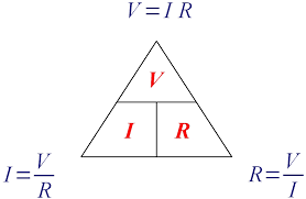
       Ohms law states that at constant temperature the current flow through a conductor is directly proportional to the potential difference between the two ends of the conductor . 

ohm's law


What is Torque Define Torque

What is Torque 


Torque 

     
     Torque is the twisting moment or turning moment of a circulating body. The unit of torque is Newton-metre.
When a force of one Newton acts on a pulley of one metre radius the torque developed is one Newton-meter.

1kg.m = 9.8 NM

what is thermal energy or heat energy

What is thermal energy or heat energy


Thermal energy

   
     Calorie is the unit of heat energy.One calorie is defined as the amount of heat required to raise the temperature of one gram of water through one degree centigrade.

Heat energy H = MST calories

where 
       M = Mass of the body in gm
       S = Specific heat of the body
       t = Change of temperature

1 calorie = 4. 86 Joules

what is emf Define emf

What is EMF


    It is the force which causes to flow the electrons in any closed circuit. the unit of electromotive force is volt.
One volt is defined as the p.d across a resistance of one ohm carrying a current of one ampere.

What is the unit of work what is the si unit of work

What is the unit of work


Work
   
   Common symbol =  W
   
   SI Unit                 = Joule (J)

What is the unit of energy what is the si unit of energy

What is the unit of energy 

Unit of energy = Joules 

   Joule (J) is the MKS unit of energy, equal to the force of one Newton acting through one meter

what is energy

what is energy


Energy (E)
     
     Energy is the capacity to do work. The unit of electrical energy is walt sec.or joules.

Energy = power X time = P xt

Unit of energy = Joules 

 Joule (J) is the MKS unit of energy, equal to the force of one Newton acting through one meter


what is mechanical energy define mechanical energy

what is mechanical energy define mechanical energy 


Energy (E)
    
     Joule is the unit of mechanical energy joules is defined as the work done,when a force of one Newton moves through a distance of one metre.

         One joule = One watt sec 

What is work define work

What is work define work 


Work

      Work is said to be done on a body. When a force acts on it, the body through some distance. The unit of work is joule or Newton-metre.


Work =  Force X distance

Monday 4 April 2016

Explain Separately excited generator

Separately excited generator

     When the field winding is supplied from external separate d.c supply i.e excitation of field winding is separate then the generator is called separately excited generator .

separately excited generator


     The field winding of this types of generator has large number of turns of thin wire. So length of such winding is more with less cross-sectional area. So resistance of this field winding is high in order to limit the field current .

Friday 1 April 2016

Fleming's right hand rule

Fleming's right hand rule

Fleming's Right Hand Rule
     
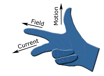
     If three fingers of a right hand namely thumb, index finger and middle finger are outstretched so that everyone of them is at right angles with the remaining two and if in this position index finger is made to point in the direction of lines of flux, thumb in the direction of the relative motion of the conductor with respect to flux then the outstretched middle finger gives the direction of the e.m.f  induced in the conductor .


image of right hand rule

What is armature winding

What is armature winding 

 Armature winding
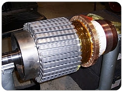
    An arrangement of conductors to form a winding in which e.m.f. is induced .This is called an armature winding .


armature winding
 

What is field winding

What is field winding 

Field winding 

     An arrangement of winding which is used as a primary source of flux when current is passed through it. This is called field winding or exciting winding .


Faraday's Law of electro magnitic Induction

Faraday's Law of Induction 

Law of Electromagnetism


     A law stating that when the magnetic flux linking a circuit changes, an electromotive force is induced in the circuit proportional to the rate of change of the flux linkage.


        d0
e =  -----
         dt


types of LDB

types of LDB

types

         LDB  - Lighting Distribution Board

          MLDB  - Main Lighting Distribution Board

           SLDB  -  Secondary Lighting Distribution Board
 
           ELDB  -  Emergency Lighting Distribution Board

What is the full meaning of VFD

What is the full meaning of VFD


VFD - Variable Frequency Drive


What is the use of DO fuse

What is the use of DO fuse 

DO fuse or Fuse cut out

     In electrical distribution, a fuse cutout or cut-out fuse is a combination of a fuse and a switch, used in primary overhead feeder lines and taps to protect distribution transformers from current surges and overloads. An overcurrent caused by a fault in the transformer or customer circuit will cause the fuse to melt, disconnecting the transformer from the line.


abbreviation of DO Fuse

Abbreviation of DO Fuse


DO Fuse   - Drop Out Fuse

what is the full meaning of HT and LT

what is the full meaning of HT and LT

Full form of HT & LT
  '
        HT  - High Tension 

        LT  - Low Tension
        
        EHT -  Extra High Voltage

Tension is the French Language and the equivalent English translation is Voltage

LT - Low Tension ( Low Voltage )
        
Low tension lines have low voltage less than 1000 volts and high current distribution system Example of 440V 3 phase supply and 230v Single phase supply.commonly we used LT  in Secondary distribution system like our household applications are working in LT. It is used to transmit power at very small distances and use thicker conductor.
 ( P= VX I ) 
Here Low voltage and higher current , conductor size depending up on current.

HT - High Tension ( High voltage )
  
High Tension lines are using higher voltages ( 11kV, 33kV, )  it is used to Distribute power to large distances by in creasing voltage and decreasing current so as to reduce I^2 R losses. HT line uses thinner conductors than LT  line conductor.

EHV - Extra High Voltage 

Extra High voltages are using much higher voltages ( above 33 kV to 700 kV )  It is used in Transmission system to transmit higher power.


what is the full meaning of ACVS

what is the full meaning of ACVS

Abbreviation of ACVS
    
      ACVS - Air Conditioning and Ventilation System

What is the full meaning of AB Switch

What is the full meaning of AB Switch

Abbreviation of AB Switch 

        
      AB Switch - Air Break Switch

Image 


Explain AB Switch

Explain AB Switch 

    AB switch  - Air Break Switch


Construction 


  The Air break Switch  have triple pole construction and will be suitable for Vertical / Horizontal mounting. Each pole consist of galvanized steel base, insulators of reputed make, copper alloy male and female contacts, arcing horns of adequate section to break magnetizing current of transformer. M.S. square coupling rod of adequate length for rocking operation, required length of G.I pipe for operation from ground level and operating handle is specially design for smooth operation. Adjustable pins are provided to limit over travel of moving post. Ferric parts are hot dip galvanized and non-ferric parts are heavily tinned to withstand weather. Jumper is of EC grade braided tin plated copper of appropriate size to complete the current path from moving post to fix post.

what are the types of relay

  Types of relay

Types 

        1.       Latching relay
        2.       Reed relay
        3.       Mercury Wetted relay
        4.       Mercury relay
        5.       Polarized relay
        6.       Machine tools relay
        7.       Coaxial relay
        8.       Time delay relay
        9.       Solid state relay
       10.   Solid state contactor relay
       11.   Buchholz relay

Thursday 31 March 2016

What is the full meaning of DPDT

What is the full meaning of DPDT


DPDT 

     Double Pole Double Throw. These have two rows of change-over terminals. Equivalent to two SPDT switches or relays actuated by a single coil. Such a relay has eight terminals, including the coil  .


What is the full meaning of DPST

What is the full meaning of DPST

DPST 

      Double Pole Single Throw. These have two pairs of terminals. Equivalent to two SPST switches or relays actuated by a single coil. Including two for the coil, such a relay has six terminals in total. The poles may be Form A or Form B (or one of each).


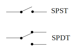
SPST DPST DPST

What is the full meaning of spdt

What is the full meaning of SPDT


SPDT 

      Single Pole Double Throw. A common terminal connects to either of two others. Including two for the coil, such a relay has five terminals in total.

SPDT SYMBOL


What is the full meaning of spst

What is the full meaning of SPST


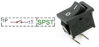
SPST 

        Single Pole Single Throw. These have two terminals which can be connected or disconnected. Including two for the coil, such a relay has four terminals in total. It is ambiguous whether the pole is normally open or normally closed. The terminology "SPNO" and "SPNC" is sometimes used to resolve the ambiguity.

single pole single throw symbol

Wednesday 30 March 2016

Explain relay

Explain relay

Relay

     A relay is an electrically operated switch. Many relays use an electromagnet to mechanically operate a switch, but other operating principles are also used, such as solid-state relays. Relays are used where it is necessary to control a circuit by a low-power signal (with complete electrical isolation between control and controlled circuits), or where several circuits must be controlled by one signal. The first relays were used in long distance telegraph circuits as amplifiers: they repeated the signal coming in from one circuit and re-transmitted it on another circuit. Relays were used extensively in telephone exchanges and early computers to perform logical operations.

A type of relay that can handle the high power required to directly control an electric motor or other loads is called a contactor. Solid-state relays control power circuits with no moving parts, instead using a semiconductor device to perform switching. Relays with calibrated operating characteristics and sometimes multiple operating coils are used to protect electrical circuits from overload or faults; in modern electric power systems these functions are performed by digital instruments still called "protective relays".

Magnetic latching relays require one pulse of coil power to move their contacts in one direction, and another, redirected pulse to move them back. Repeated pulses from the same input have no effect. Magnetic latching relays are useful in applications where interrupted power should not be able to transition the contacts.

Magnetic latching relays can have either single or dual coils. On a single coil device, the relay will operate in one direction when power is applied with one polarity, and will reset when the polarity is reversed. On a dual coil device, when polarized voltage is applied to the reset coil the contacts will transition. AC controlled magnetic latch relays have single coils that employ steering diodes to differentiate between operate and reset commands.

Symbol .


Basic design and operation

    A simple electromagnetic relay consists of a coil of wire wrapped around a soft iron core, an iron yoke which provides a low reluctance path for magnetic flux, a movable iron armature, and one or more sets of contacts (there are two[clarification needed : sets or contacts?] in the relay pictured). The armature is hinged to the yoke and mechanically linked to one or more sets of moving contacts. It is held in place by a spring so that when the relay is de-energized there is an air gap in the magnetic circuit. In this condition, one of the two sets of contacts in the relay pictured is closed, and the other set is open. Other relays may have more or fewer sets of contacts depending on their function. The relay in the picture also has a wire connecting the armature to the yoke. This ensures continuity of the circuit between the moving contacts on the armature, and the circuit track on the printed circuit board (PCB) via the yoke, which is soldered to the PCB.

When an electric current is passed through the coil it generates a magnetic field that activates the armature, and the consequent movement of the movable contact(s) either makes or breaks (depending upon construction) a connection with a fixed contact. If the set of contacts was closed when the relay was de-energized, then the movement opens the contacts and breaks the connection, and vice versa if the contacts were open. When the current to the coil is switched off, the armature is returned by a force, approximately half as strong as the magnetic force, to its relaxed position. Usually this force is provided by a spring, but gravity is also used commonly in industrial motor starters. Most relays are manufactured to operate quickly. In a low-voltage application this reduces noise; in a high voltage or current application it reduces arcing.

When the coil is energized with direct current, a diode is often placed across the coil to dissipate the energy from the collapsing magnetic field at deactivation, which would otherwise generate a voltage spike dangerous to semiconductor circuit components. Such diodes were not widely used before the application of transistors as relay drivers, but soon became ubiquitous as early germanium transistors were easily destroyed by this surge. Some automotive relays include a diode inside the relay case.

If the relay is driving a large, or especially a reactive load, there may be a similar problem of surge currents around the relay output contacts. In this case a snubber circuit (a capacitor and resistor in series) across the contacts may absorb the surge. Suitably rated capacitors and the associated resistor are sold as a single packaged component for this commonplace use.

If the coil is designed to be energized with alternating current (AC), some method is used to split the flux into two out-of-phase components which add together, increasing the minimum pull on the armature during the AC cycle. Typically this is done with a small copper "shading ring" crimped around a portion of the core that creates the delayed, out-of-phase component,[9] which holds the contacts during the zero crossings of the control voltage.


Explain electrical contactor

Explain electrical contactor


Contactor .

    A contactor is an electrically controlled switch used for switching an electrical power circuit, similar to a relay except with higher current ratings. A contactor is controlled by a circuit which has a much lower power level than the switched circuit. Contactors come in many forms with varying capacities and features.

Parts .


    A contactor has three components. The contacts are the current carrying part of the contactor. This includes power contacts, auxiliary contacts, and contact springs. The electromagnet (or "coil") provides the driving force to close the contacts. The enclosure is a frame housing the contact and the electromagnet. Enclosures are made of insulating materials like Bakelite, Nylon 6, and thermosetting plastics to protect and insulate the contacts and to provide some measure of protection against personnel touching the contacts. Open-frame contactors may have a further enclosure to protect against dust, oil, explosion hazards and weather.

Magnetic blowouts use blowout coils to lengthen and move the electric arc. These are especially useful in DC power circuits. AC arcs have periods of low current, during which the arc can be extinguished with relative ease, but DC arcs have continuous high current, so blowing them out requires the arc to be stretched further than an AC arc of the same current. The magnetic blowouts in the pictured Albright contactor (which is designed for DC currents) more than double the current it can break, increasing it from 600 A to 1,500 A.

Sometimes an economizer circuit is also installed to reduce the power required to keep a contactor closed; an auxiliary contact reduces coil current after the contactor closes. A somewhat greater amount of power is required to initially close a contactor than is required to keep it closed. Such a circuit can save a substantial amount of power and allow the energized coil to stay cooler. Economizer circuits are nearly always applied on direct-current contactor coils and on large alternating current contactor coils.

A basic contactor will have a coil input (which may be driven by either an AC or DC supply depending on the contactor design). The coil may be energized at the same voltage as a motor the contactor is controlling, or may be separately controlled with a lower coil voltage better suited to control by programmable controllers and lower-voltage pilot devices. Certain contactors have series coils connected in the motor circuit; these are used, for example, for automatic acceleration control, where the next stage of resistance is not cut out until the motor current has dropped .

Operation .


    Unlike general-purpose relays, contactors are designed to be directly connected to high-current load devices. Relays tend to be of lower capacity and are usually designed for both normally closed and normally open applications. Devices switching more than 15 amperes or in circuits rated more than a few kilowatts are usually called contactors. Apart from optional auxiliary low current contacts, contactors are almost exclusively fitted with normally open ("form A") contacts. Unlike relays, contactors are designed with features to control and suppress the arc produced when interrupting heavy motor currents.

When current passes through the electromagnet, a magnetic field is produced, which attracts the moving core of the contactor. The electromagnet coil draws more current initially, until its inductance increases when the metal core enters the coil. The moving contact is propelled by the moving core; the force developed by the electromagnet holds the moving and fixed contacts together. When the contactor coil is de-energized, gravity or a spring returns the electromagnet core to its initial position and opens the contacts.

For contactors energized with alternating current, a small part of the core is surrounded with a shading coil, which slightly delays the magnetic flux in the core. The effect is to average out the alternating pull of the magnetic field and so prevent the core from buzzing at twice line frequency.

Because arcing and consequent damage occurs just as the contacts are opening or closing, contactors are designed to open and close very rapidly; there is often an internal tipping point mechanism to ensure rapid action.

Rapid closing can, however, lead to increase contact bounce which causes additional unwanted open-close cycles. One solution is to have bifurcated contacts to minimize contact bounce; two contacts designed to close simultaneously, but bounce at different times so the circuit will not be briefly disconnected and cause an arc.

A slight variant has multiple contacts designed to engage in rapid succession. The first to make contact and last to break will experience the greatest contact wear and will form a high-resistance connection that would cause excessive heating inside the contactor. However, in doing so, it will protect the primary contact from arcing, so a low contact resistance will be established a millisecond later.

Another technique for improving the life of contactors is contact wipe; the contacts move past each other after initial contact in order to wipe off any contamination


Wednesday 23 March 2016

What is the full meaning of SF6 breaker

What is the full meaning of SF6 breaker

SF6 circuit breaker - sulphur hexafluoride Circuit  Breaker 
 

What is the types of circuit breaker

What is the types of circuit breaker


Types of Circuit breaker

     1. Low voltage circuit breaker
     2. Medium voltage circuit breaker
     3. High voltage circuit breaker

1. Low voltage circuit breaker

    Low-voltage (less than 1,000 V)

    Types .

1.    MCB
2.    MCCCB
3.    ACB

  2 . Medium voltage circuit breaker

        Medium-voltage circuit breakers rated between 1 and 72 kV.

Types

    Medium-voltage circuit breakers can be classified by the medium used to extinguish the arc .
1.    Vacuum circuit breakers—With rated current up to 6,300 A, and higher for generator circuit breakers
2.    Air circuit breakers—Rated current up to 6,300 A and higher for generator circuit breakers. Trip characteristics are often fully adjustable including configurable trip thresholds and delays. Usually electronically controlled, though some models are microprocessor controlled via an integral electronic trip unit .
3.    SF6 circuit breakers extinguish the arc in a chamber filled with sulphur hexafluoride gas.


3 .High  voltage circuit breaker.

   The definition of high voltage varies but in power transmission work is usually thought to be 72.5 kV or higher, according to a recent definition by the International Electrotechnical Commission (IEC)

Types

1.    Air blast circuit breaker
2.    Vacuum circuit breaker
3.    SF6 Circuit breaker
4.    CO2 Circuit breaker